Showing posts with label CRT Repair. Show all posts

Epson QX-10 - One of the Last CP/M Machines

The Epson QX-10 is a sleek looking design from the early 80's.  It is from the tail end of the CP/M Era and it's a really neat looking machine.  My experience with the QX-10 started when a friend was demonstrating his at a local Retro meet up hosted by Free Geek.  It turns out he had a second machine in need of repair and since he's already got a very nice one, I was able to acquire that second machine from him, thanks again, Steve!

I started working on this in the Fall of 2025 when I acquired the machine.  There was no cable included to attach the custom CRT to the base unit.  This cable brings both power and signals from the base unit to the CRT and so it's difficult to begin testing without that.  There is a replacement cable avaliable online, so I ordered one of those.  With the cable installed I could see that the machine was powering up to the "Insert Diskette" prompt.  This is a very good sign because it means that the processor is running and whatever diagnostic checks are built into the ROM are passing.

As with most CP/M machines that don't have a hard drive the A drive is used constantly to boot and run the machine, so the A drive often needs special attention.  This machine was no exception.  The floppy drives were manufactured by Epson themselves.  In order to maintain the sleek form factor of the machine they made these drives 1/3 height, not a standard 1/2 heigh drive, so these can not be easily replaced.  Knowing this I took my time removing the drives and cleaning and lubricating the mechanisms.  They were so jammed that I could not even insert or remove floppy disks from the mechanism.  With the floppy drives working, I could move on to the next phase of the repairs.

I made some floppy boot disks using my flux disk imaging setup that I've discussed before, but unfortunately my normal workflow did not work because these machines have a very unusual disk geometry so the first round of disks I created were not able to boot the machine properly.  But I did get far enough to type characters in to the screen and this is when I noticed the next challenge, the keyboard was not working.

This keyboard, the Epson Q603A, is a special one designed for the word processing software called ValDocs.  There is some good information on Deskthority about the keyboard.  This is a foam and foil keyboard, so I was not concerned because I've repaired several foam and foil boards over the years using the replacement kit from TexElec.  However, sadly, this board used a prototype switch with a much lower profile of foam and the normal replacement pads would cause the switches to remain pressed all the time.  I emailed TexElec about this and I was very happy to learn that they were already working on a low profile foam pad.  I got a set of these and installed them and the keyboard is working again as expected, one more step closer to getting this machine back on the road.

At this point because of my problems getting booted up and not have known good boot disks I stalled out on the project and set it aside.  But within a few weeks I saw a relevant post on the Vintage Computer Federation forums where I hang out, so I chimed in on there.  I received some great feedback about my disk imaging problem from one of the members there and I was able to create some new boot disks using a different starting point.  These boot disks worked and I could see that the Epson was fully booting up into an operating system.

Unfortunately, as often happens with Retro Computers, just when we think a project is ending, something else broke.  The CRT display starting rolling and I couldn't get the video to stabilize.  This CRT has only one adjustment for brightness on the outside so I took the case off to get inside.  I went through all the potentiometers on the circuit board and put Deoxit Fader Lube on them and cycled them back and forth.  I also did a careful inspection.  I was not able to identify anything wrong. After plugging everything back in it started working again.  I think there may be an intermittent connection with one of the sync signals so I'm going to try to isolate that to the Monitor side or the Computer side and maybe reflow the solder joints on those circuit boards.

But for now, the machine boots and runs, and it's time for me to explore one of the last and most modern looking of the CP/M machines.  I'm really glad to have this machine in the collection as it very much has the look of the era it came from...

Did you use CP/M back in the day?  Do you have memories of the Epson QX-10 or the Valdocs software?  If so leave a comment below, or drop me an email at my address in my profile, I'd love to hear about your experiences.

Wang Professional Computer from 1984

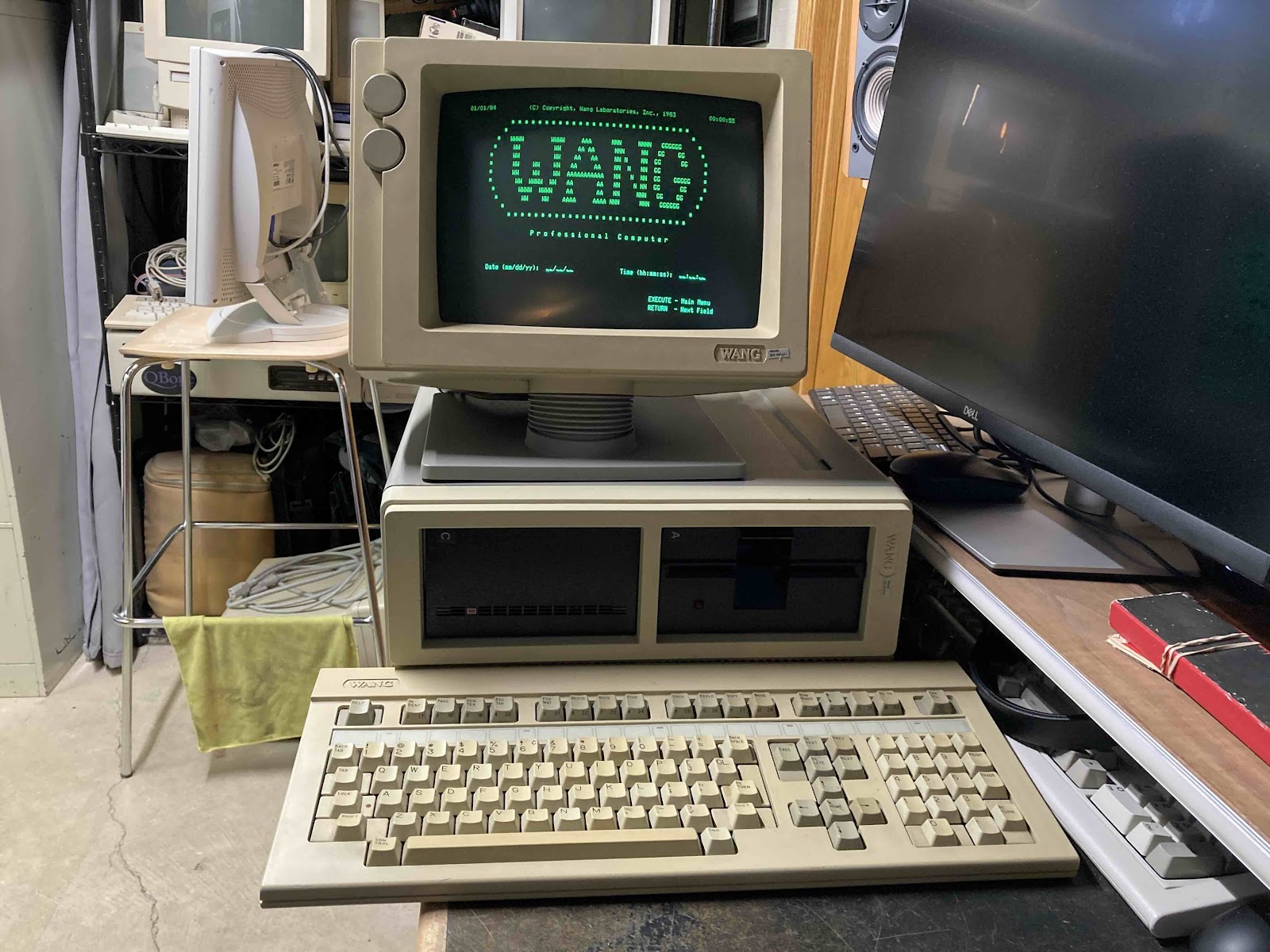
 At the end of last year (Dec 2024) I was browsing Facebook Marketplace and saw a somewhat interesting computer that I had never heard of before, a Wang Professional Computer (Wang PC).   I've been interested in Wang since learning about the history of the company founder, An Wang, and his contributions to the history of computing.  He was involved in the development of Core Memory, and was able to use the funds from the sale of that invention to start his computer company Wang Laboratories.

I was interested in the Wang PC but did some research before buying it.  Because this is not IBM PC compatible, you need the custom Wang Keyboard and a custom monitor to use this machine.  The Facebook listing included a Keyboard but not a Monitor.  I was going to take a pass on the machine, but the seller lowered the price to the point that I could not refuse. 

I took the Wang PC apart and did some light cleaning and dusting inside of the case.  The computer appears to be in good shape.  Then it went up on a shelf in storage waiting for a time when I could find a matching CRT at a reasonable price.

Fast-forward 4 months.  I had a saved search for Wang CRT monitors on eBay, and a compatible monitor appeared.  I got the Wang PC down and tested it out to see if the Power Supply was working and if the computer was showing any signs of life without the monitor.  The computer did appear to be working, at least as well as I could tell without a monitor, and I thought it was even booting from the internal Hard Drive.  So I ordered the specialized CRT from eBay.  I was a bit nervous becuase the screen was not guaranteed to work.  But the seller did a great job of packing it and it arrived intact.

I was super happy when I powered the system up with the monitor for the first time and it worked!  Then only a few seconds later, the CRT's horizontal sweep collapsed to a vertical line, what a bummer...


Thankfully I have been able to fix simple CRT problems in the past so I took the monitor apart and started troubleshooting.  I was not able to find a service manual or a schematic, but the circuit board was well labelled.  That is about the best I can say about the circuit board.  When I started removing components to test out of circuit I damaged several traces as they were not stuck to the board very well.  It took me quite a few hours over a couple of different evenings to get the monitor working again, I never did identify a bad component.  I did reflow most of the solder joints on the monitor board so it was likely a cold solder joint from vibration or old age, or the low quality of the circuit board.  Either way the monitor is working again and the Wang PC is usable!


But, then I encountered the next issue, the keyboard was not working well.  I did get a few key presses to register but most of the keys didn't work at all.  Then the ones that had worked stopped working, too.  This was not a huge surprise as I had already read that this was a "Foam and Foil" type keyboard.  I've restored a couple of other brands of these type using these pads that are sold by TexElec so I got another set of those on order and prepared the keyboard by taking it all apart, removing the old pads and doing a through cleaning.  After replacing all tbe pads I did some testing and then fully re-assembled the keyboard.  All the keys appear to be working and I'm quite happy with how it turned out.

Once the keyboard was complete, I was able to explore the computer and see what files were present on the hard drive.  The 10MB hard drive is about 1/2 full.  The drive appears to be working well, it's not making any unusual sounds so that's good.  One interesting feature of the machine is a simple menu that starts up on boot, it allows the user to move around without typing any commands to start programs and move files around...


This machine has the Wang Word Processor installed.  Wang was famous for this.  They had dedicated hardware just for word processing in their previous generation of hardware, which you can see covered on Usagi Electric.  Although my machine is a General Purpose computer, Wang Word Processing is just about the only software installed on this machine.


I tested the Floppy Drive a bit, and it did not seem to be working correctly.  It was functional for a little while, then stopped working.  I took the machine apart and did some cleaning.  I re-seated connectors but there was nothing obvious wrong with the drive.  When I re-assembled in, the drive started working!  I was able to boot the machine from Floppies I had made from Drive Images I found on WinWorld.

And with that repair, the Wang PC is functionally complete!  I'm very happy to have this system.  It will go nicely with my other MS-DOS compatible machine, the Tandy 2000, and maybe this will motivate me to work on another MS-DOS system I've had in storage for a while, a Zenith Z-100 system.

A Kaypro II from 1982

My latested repair story is about a Kaypro II from 1982.  The Kaypro machines have such an odd numbering scheme.  They used Arabic numerals and Roman numerals to refer to different computers, it is so confusing that collectors have taken to referring to them by the year of their release.  The Kaypro II 82 is a different computer from the Kaypro 2 84 released two years later.  There is so much confusion caused by this so many articles online contain inaccuracies in describing the features and functions of the machines.

I've had a Kaypro 2 84 for several years, and acquired a Kaypro 1 from 1986 last year, but I've long wanted a Kaypro II 82 both for historical reasons, because it's the first of an iconic line of CP/M computers, and also for nostalgic reasons because my uncle who bought me my first computer bought one of these machines for my Grandpa and Grandma.  I knew from day one that Grandpa and Grandma's machine was a much more serious tool than the one that I had, and I thought it has an amazing design, it looked like a "real computer".

This Kaypro II 82 came from Free Geek Twin Cities via my friend Chris Gallaty.  Special thanks to Chris for getting this machine when he did and for passing it on to me.  The machine came with a note "Powers On - Keyboard Cable Needs Simple Repair".  One of the basic rules of troubleshooting is that you should not take other people's troubleshooting work at face value, you always want to do that work yourself, but I was hopeful that the label was correct.

The plug on the keyboard port had been smashed in and that repair did need to be done so I started out with the obvious repair first.  Chris has also given me a 4 pin modular jack from a phone handset.  Once I got inside the Kaypro the jack inside had taken a pretty hard hit and was beyond repair, so I needed the new part.  I soldered the replacement in and hot glued it on the inside to improve the support.  It feels quite solid.

I was able to drag out another working Kaypro machine and test the keyboard.  It was working as expected!

Next, I powered up the Kaypro II machine.  The CRT came up, but the normal prompt that appears on power up was not appearing, normally the machine would have a prompt that says 

*Kaypro II*
Please Insert a Disk

This message appears before booting and so a working floppy drive is not needed to get this message, just a working power supply, main board, and CRT.  I checked the power supply voltages and they were OK.  On the CRT I did not see any raster pattern when the brightness was turned up, or after adjusting the knobs.  I did some basic troubleshooting on the mainboard, and ended up moving the main board over into a different Kaypro.  I could see that it was outputting video, so that isolated the issue to the CRT analog circuit.  This was discouraging because I'm not the best at CRT repair, but I started doing some reading and found this article on Vintage Computer Forums.  I normally don't like doing "Shotgun" repairs, but I replaced as many of the caps as I could from my stock of Capacitors and that helped, now the image looked like this...

There was raster and the CRT was displaying text!  Also, I cleaned the disk drives with a floppy cleaning disk, and I made SS/DD Boot Disks for the Kaypro II.  The machine booted from the floppy!

The non-centered but visible image was evidence that I needed to complete the recap so I captured the rest of the capacitor sizes and put in an order on DigiKey.  When the caps arrived and I had time to get back to repairs on this machine I identified a large capacitor that was totally dead, so once the recap was complete, the image looked great and I completed the CRT adjustments.  I now have a fully functional Kaypro II machine...

I feel quite fortunate to have one of these systems, it's been on my wish list for quite some time.  My next project for the Kaypro II 82 will be make some more floppy disks.  I'm also thinking about swapping one of the drives for a Go-Tek as it would be really cool to be able to boot and run from Flash Storage.

NeXT Megapixel Display N4000A Repairs

 As you may have seen previously on my blog, I'm fortunate to be the custodian of a NeXTStation setup that I purchased at last year's Vintage Computer Festival - Midwest.

Since blogging about that machine, I've recapped the mainboard, added an External SCSI CD-ROM so I can load software the old fashioned way, and upgraded the Hard Drive to a 2GB Quantum Fireball (Fingers crossed, it's still working!).  One outstanding issue with the machine has been that the audio on the monitor has not worked since I owned the machine.

According to this article, on the nextcomputers.org forum, it was likely that a circuit board in the monitor need to be recapped.  I finally got the time to tear into the monitor and have a look.  What I found surprised me, and so I thought I'd put this out here for the community so you can potentially avoid these pitfalls.

First let me start with the obligatory warning about working inside of CRTs.  I recommend you not do what I've done. If you do decide to go ahead, then watch a video or three about how to properly discharge a CRT before you work on it.  OK now that that's over with...

First, it was pretty easy to tear down the monitor, but I did make a mistake along the way removing the stand from the bottom of the monitor.   You don't need to do that, and if you do release the tension on the monitor stand's hinge, it's difficult to get that back in adjustment, so I'd recommend that you not remove the stand or mess with the hinge.

The back comes off with four Allen screws...


This exposes the old school RF shielding.  I'd recommend putting this back on when you are done (I'm looking at you Adrian Black).  The shielding is held on by four screws on one side and five screws on the other, they are all the same length.   When they are off, the housing comes back just a bit to release from some tabs, then can go straight up off the monitor...


This exposes the entire CRT and both boards.  Now would be the time to discharge the CRT if you were following along, which of course you are not because this is dangerous...


The main circuit board cover the back of the monitor, but the sound board is on the bottom of the enclosure.  It cannot be removed without taking the electronics off the chassis, but this is pretty easy to do.  

On the bottom of the monitor, there are two large screws that hold the electronics portion of the chassis onto the sub-frame that holds the tube and the stand.  Removed these two screws...


Disconnect all the cables from the tube, including the high voltage, the yoke, and the tube socket at the end of the tube.  Once they are disconnected, the rear of the chassis with the electronics on it can be pulled straight back.  It may be easier to pull it back just an inch to get your hand in to remove the socket from the end of the CRT.  Once all the wires are de-routed the electronics are more accessible...


The large circuit board must come off the back first before the connector board with the sound circuit can be removed.  There are two connectors going from the large board on the back to the small board on the bottom, remove those.  There are five screws holding it in.  Remove the screws and set the large board aside.  Note:  I did a careful inspection and some cleaning on this board, but I did not see any of the small electrolytic capacitors on this board, so I didn't do any recapping on this board at this time.

The small circuit board is held in by two screws inside, and two nuts on the outside of the enclosure where the cable attaches, remove those...


The circuit board has a Dozen (12) Electrolytic Capacitors. They are 47uF, 16 V rated caps...


Remove and replace the caps.  In this case the monitor was from 1991 and so it was suffering from capacitor leakage and needed some minor rework on a couple of the traces.  I'm glad I caught this in time.

But, there was one more twist in the story.  When I tested the monitor, the audio was not restored to function.  After measuring resistance on the speaker, it was open circuit.  I was able to source a replacement speaker from Rob at Black Hole, Inc, and the monitor and speaker are now functioning normally.

The final hardware upgrade I'm planning for this machine is to replace the Spinning HDD with a Solid State device, but in the meantime I've got alot of learning to do about how this machine works and what its capabilities are.